 |
 |
 |
 |
 |
 |
 |
 |
 |
 |
|
|
|
|
|
|
|
|
|
|
|
|
|
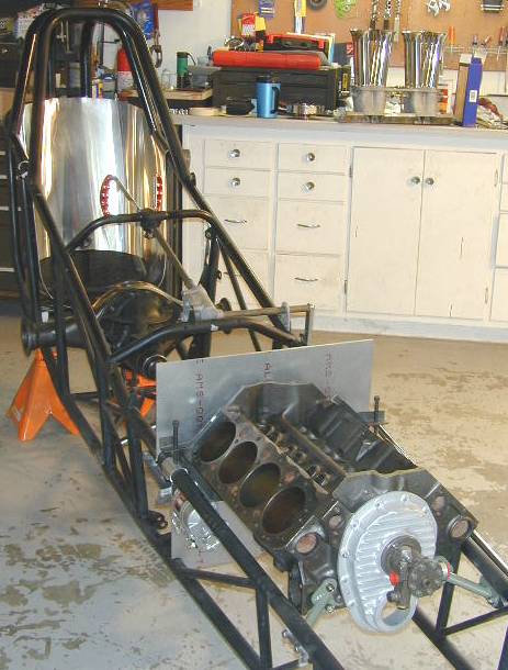
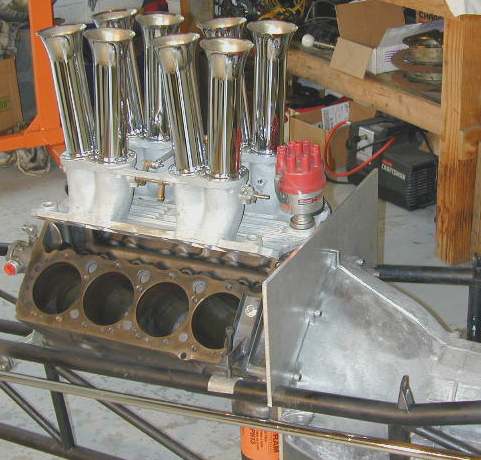
I totally dissassembled the entire car. Using a "Sawz-all" and a grinder, I cut most of the existing brackets off and carefully took the welds down to the frame rails. I checked over every square inch of the car and managed to find one small crack in the right lower frame rail just behind the fuel tank area. It will be easily repaired.I hauled the bare chassis up to Woodburn and had it certified down to 7.500 second ET's for another 3 years. I decided to move the engine as far ahead as possible so that a minimum of useless ballast would be needed to keep the front wheels down. I moved it ahead 3", limited by the fact that M&W couplers are only available up to 8" in length. 1 1/2" of engagement with the tranny tailshaft is needed, and I didn't want to go with an actual driveshaft. A new coupler was ordered and front motor mounts were built. Instead of using hose clamps to hold the front of the motor down, small triangular plates were added in the crotch of a chassis brace just in front of the engine block. Small tubular mounts bolting to the plates and then to the front of the engine were constructed. They look nice!
Instead of using a mid-plate for the motor and a separate firewall, I chose to combine the two. A 2'x2'x.250" aluminum plate was purchased and holes were cut for the frame rails. In the photos above, the curve that the cowl will follow has yet to be put on and there still is no crankshaft hole. With the injector and distributor in place, it's easy to visualize where the cowl will be. In the photos, you can see some screw brackets bolted to the engine deck surface. These allow fine adjustment of the engine altitude and angle for the purpose of aligning the drive coupler to the rearend. There are no u-joints to correct for error...it has to be perfect!
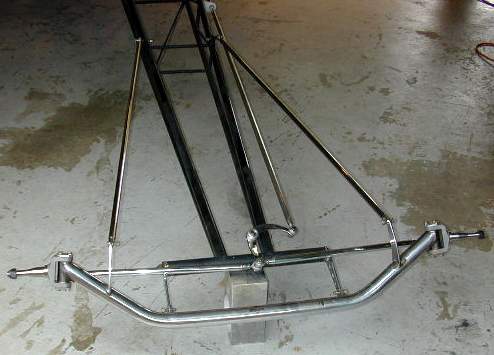
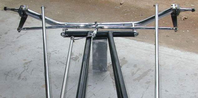
The worn out, ancient English Ford Anglia spindles were retired in favor of brand new chrome-moly units, effectively narrowing the front axle a few inches overall. A new method of pivoting the steering bellcrank has been employed. The bellcrank is captured between nylon washers and aluminum discs held apart with a sleeve that serves as a bearing surface. A new chassis tab to mount this has yet to be added. I turned new bushings for the front torsion tube out of aluminum, as the old ones were shot. I managed to straighten the severly bent radius rods, and one of the steering tubes needed a tweak as well.
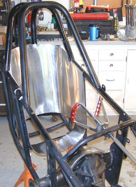
A new seat has been partially constructed...the portion that wraps around is complete, but the ass-pan is still being formed with a sandbag and a mallet. A new steering wheel has been bolted to a newly machined hub for the steering shaft. The steering box has been cleaned up and the old loose threads heli-coiled.
A new aluminum fuel tank has been designed and mocked up in cardboard. I'm now thinking of chopping it down to 4 gallons from it's current proposed 5.6 gallons. Even though alcohol is consumed at twice the rate of gasoline, I don't think I'll need that much! Body panels have also been mocked up in cardboard.
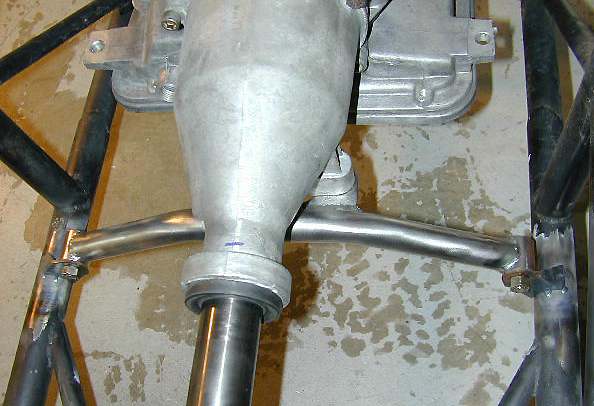
The front cover and fuel pump are in place to find out if the new harmonic balancer would fit. It was close! The starter and an oil filter are also in place to check the fit between the frame rails and other components. A new crossmember was constructed to hold up the tranny tailshaft, and a new bracket attaching the bottom of the differential to the center of the chassis was added. The old ones weren't very elegant!
Since the block has been busy posing in the car for the construction of other parts, no machine work has been done. No progress on a Powerglide either. I have been collecting engine components however! So far these parts have been purchased:
- Hilborn injector, pump, cover and breather
- Canfield aluminum cylinder heads
- 6.000" H-Beam connecting rods
- Pete Jackson Gear Drive
- Power Master High-Torque 4.41:1 gear reduction starter
- Fluid-damper harmonic balancer
- Flex Plate
- Main cap studs
- 4340 forged 3.500" stroke (+.020 long!) crankshaft
- 2.05" & 1.60 Stainless Steel valves
- Mallory Electronic Advance distributor